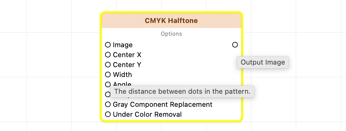
In any node-based development environment, it can be hard to interpret the inputs and outputs of a node. FxCore uses tooltips extensively to fill in necessary details. Move the mouse cursor over any output to display any description or instructions available for that port:
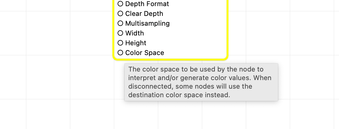
In some cases, the tooltip is the only way to explain some of the more advanced features and behaviors of the node. Take, for example, the explanation given for the Color Space input to the 3D Render to Texture node:
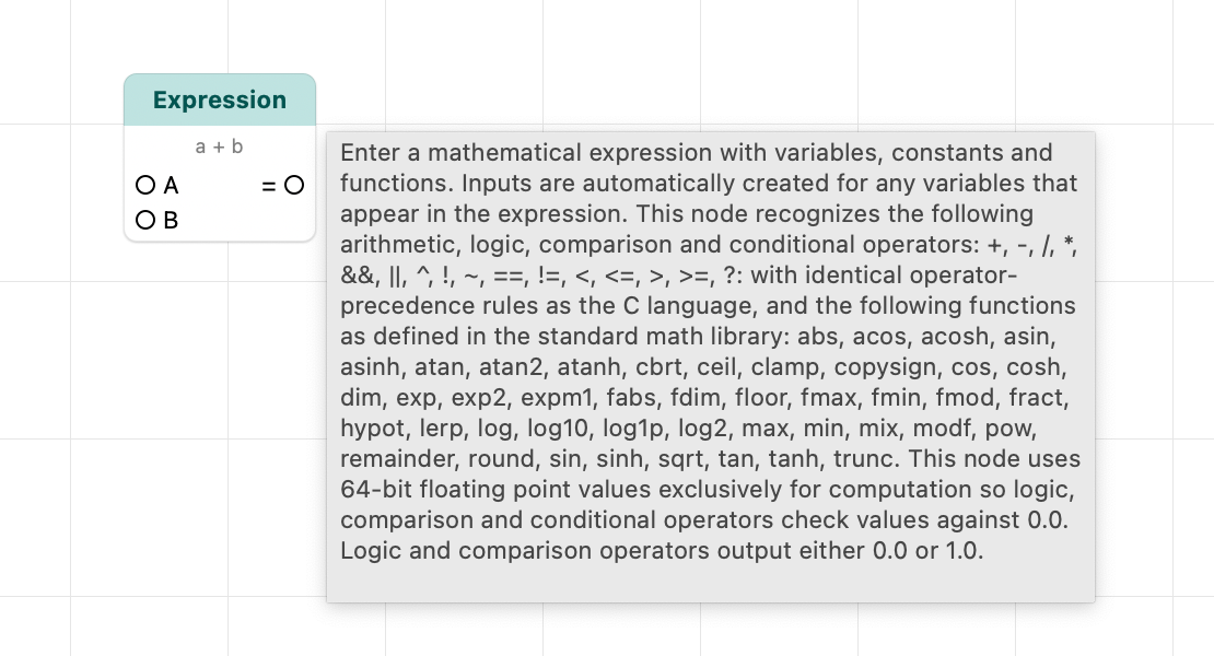
When pausing the cursor on the node’s header, the tooltip displays general documentation for that node. This is the same information you can read in the Library browser.
Sticky Tooltips
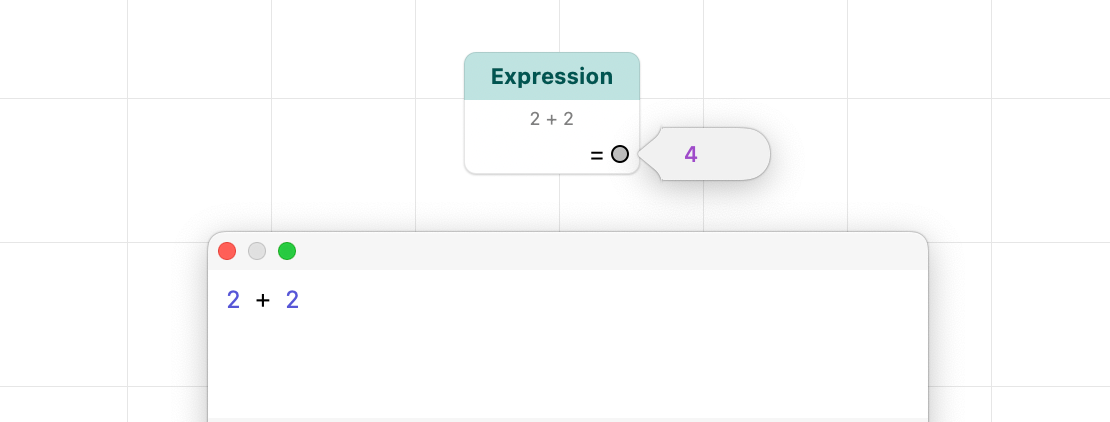
Since you’ll be using FxCore to create complex visual effects, one of the first problems you’ll encounter is understanding what each step in the graph is doing. Click on any given output port to display its value through a second type of sticky tooltip:
When dealing with image outputs, this helps you visualize what each filter is doing with/to its inputs:
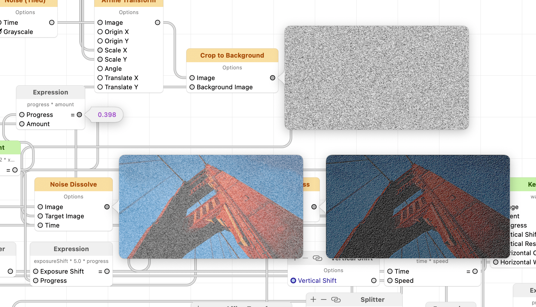
These are live previews. While the composition is playing, previews update at each rendered frame. And since we have a sick, twisted love for tooltips, these live previews can have tooltips of their own. Moving your cursor over an image will reveal more:
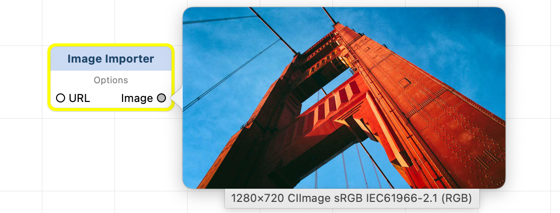
Since the previews contain a scaled-down version of the image, the tooltip reveals its native dimensions. If the image happens to have a color space associated with it, a human-readable description of the color space is included.
When color space info is missing from the tooltip, the image is the result of a computation (such as a series of Core Image filters) whose output cannot be expressed in terms of a single color space. Such image recipes are assigned a color space only when rendered to an actual surface. Commonly the output color values are expressed in the color space of the current rendering destination. When working in the FxCore application, the destination color space is, by default, the color space of your built-in display. Some container nodes, such as 3D Render to Texture let you optionally create its output in a different color space. When the composition is used by FxFactory in a visual effect plug-in, the destination color space is determined by the host application – commonly a linear or gamma-correected variant of Rec. 709, 2020, 2100, etc.)
Tooltips may also mention the underlying API used to represent the image, such as “Core Image” or “Core Graphics”. This information only pertains to the base representation for that image, since FxCore automatically creates and caches multiple representations of that image, as needed, in various other formats.
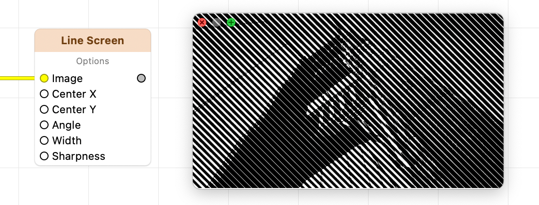
Live previews remain anchored to their corresponding output. What if you need to keep one of these live previews visible as you scroll to a different section in the graph? Click on the preview and drag it away to detach it to a separate floating window:
Impressive, right? Beginning with FxCore 8.0.22, these previews are capable of displaying Wide Gamut HDR content, just as the main output of the composition. This can be very helpful when diagnosing problems in complex graphs.
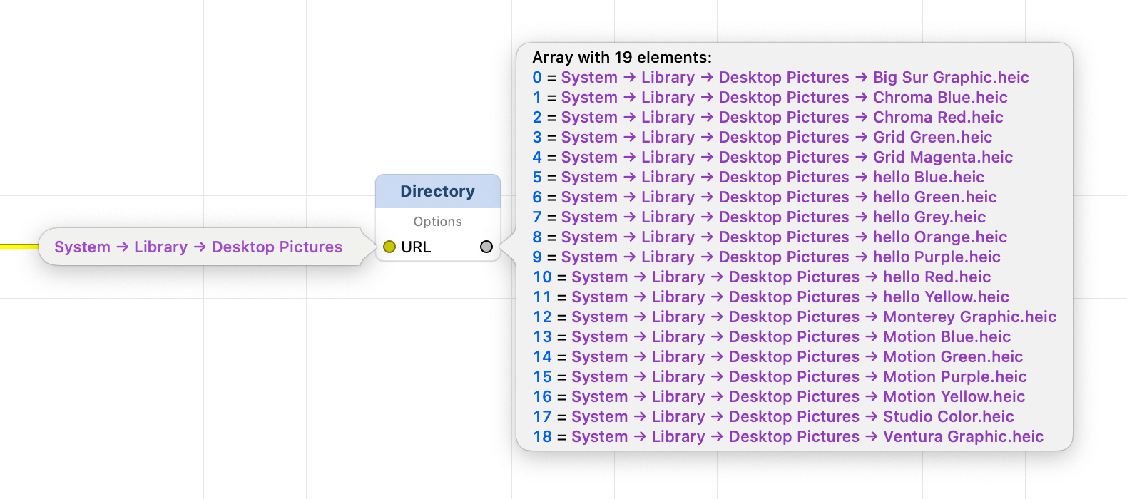
FxCore provides summarized and/or formatted output. For example an array of file URLs as produced by the Directory Scanner will use special formatting for each path:
You’re not telling me the whole truth!
Indeed. The behavior when clicking on output ports is always to display a live preview of its value. When clicking on an input, FxCore provides (whenever possible) a small widget to let you specify the input. This value editor often replicates the user interface available in the inspector:

Here is how one of the inputs and final output of the Create Color node are displayed:
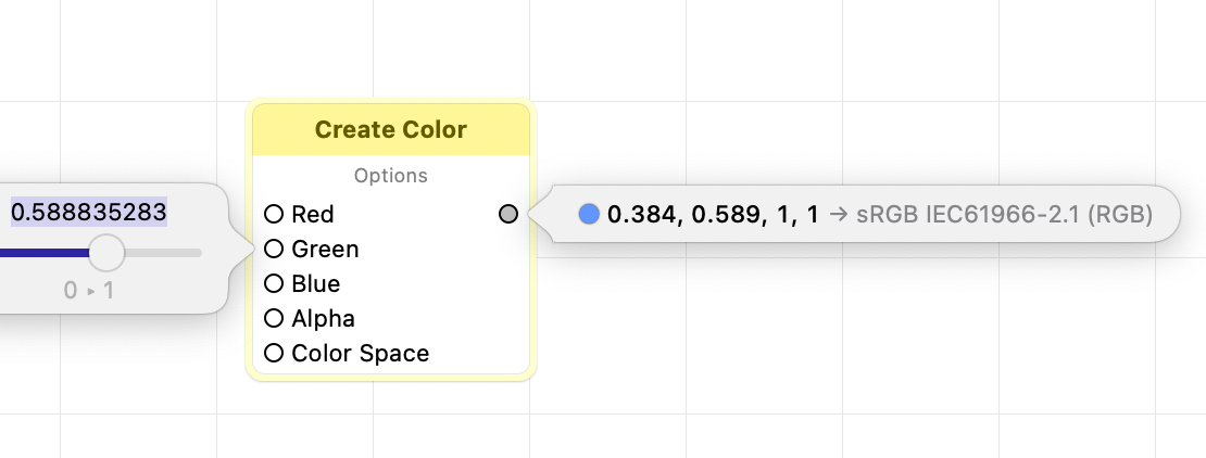
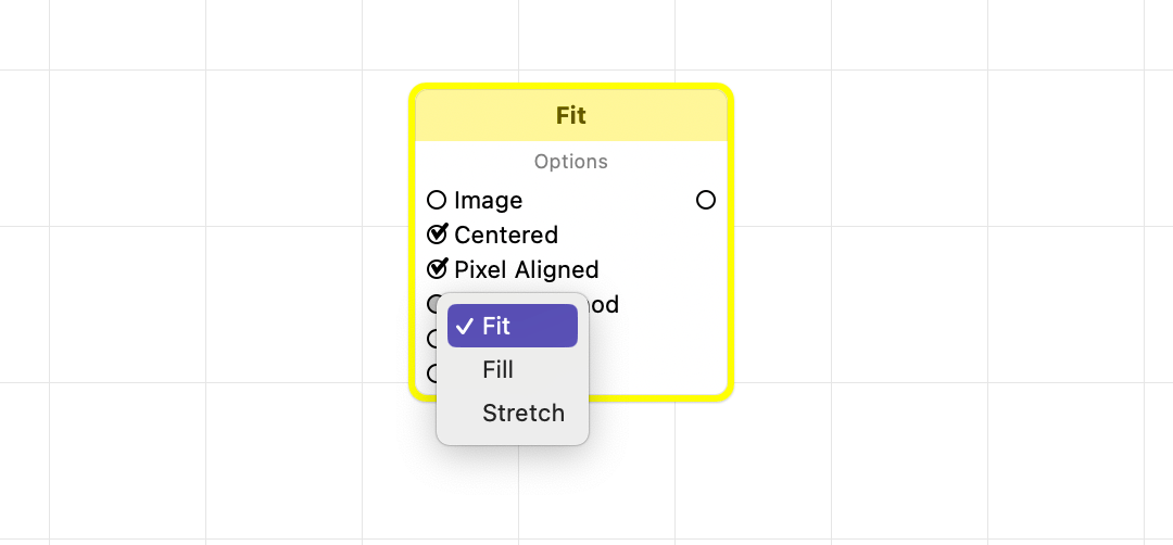
Notice the special formatting used to display a color value, spelling out values for individual components as well as its color space. Multiple-choice inputs are easily specified through a popup menu:
But not all inputs can be assigned through a widget. When clicking on input URLs (aka file locations) FxCore displays a standard Open/Save dialog if it has direct knowledge of how the URL is used by the node. For example, clicking the input URL of the Image Importer node displays an open panel where only compatible image files are selectable.
If there is no appropriate method to assign a value to the input via custom UI or a file selection panel, FxCore will not take any action in respose to your click.
What happens when a port is connected?
FxCore can always display live previews for any output of a node. Whether the value is fed downstream, through a connection, has no influence over this functionality.
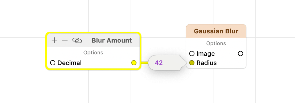
Connected inputs are a special case. When the value of an input comes through a connection, it would make little sense to allow editing of that value. The value will always, necessarily, come from the other end of the connection. Clicking on a connected input will therefore display a live preview of the value, as fed to the node through the connection: